Home Made Rock Slider Fabrication

Upgrades and modifications to Trims, Seats, Carpets, Roof Racks, Panels, Dashboard, Bumpers, Rocksliders, Paint, Decals...

Moderator: volvite

User avatar
dcommoncents
Posts: 53
Joined: Thu Jan 08, 2015 1:09 pm
Location: Pittsburgh, PA

Home Made Rock Slider Fabrication

Postby dcommoncents » Mon Nov 09, 2015 5:58 pm

Hey all, I'm in the process of fabricating some steel rock sliders for my rig, so I thought I'd start something of a build thread to show the process. Unfortunately, I haven't documented this process too thoroughly, but here's what I can tell/show you.

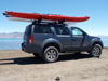
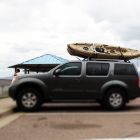
First, I went with all square 1 1/2 hot rolled steel tubing for the structure. To be honest, I can't remember the gage, but I think it's something like 1/8 inch. Not super beefy, but it should provide pretty decent protection without adding too much weight to my daily driver. I can't wait until some ass hat opens their door into my truck and dings their door on the sliders. Anyway, here are pictures:

First, I cut and assembled to pieces to see how they laid out together
Image

Then, I welded everything up. The hardest part was probably capping the ends. In the second picture, you'll see extra welds because I had the angle at the end wrong like an idiot. It's supposed to contour the body shape, so I had to cut it off, turn it the right way, and weld it back on.

Image

Image

Then, repeat for the other side
Image

Next, I welded in some cross braces.

Image

Finally, I ground all the welds down for a smoother finish that will look better and hopefully deter rust that would otherwise gather in the weld seams. That part sucked too because sometimes I would find occlusions in my welds or would grind too far and have to go back and fill spots in with more welding. Not fun or good for the base metal.
Image

But, it's pretty now.
Image

Next up is mounting to the frame. I'm fabricating u shaped brackets that will bolt around the frame because I don't want to compromise structural integrity by welding or drilling the frame.


User avatar
NVSteve
Sponsored Member
Posts: 1987
Joined: Thu Feb 01, 2007 11:27 am
Location: Salt Lake City

Re: Home Made Rock Slider Fabrication

Postby NVSteve » Mon Nov 09, 2015 7:42 pm

dcommoncents wrote:I can't wait until some ass hat opens their door into my truck and dings their door on the sliders.
I've had a few people bang into mine. Fine with me, since they are the ones with the damage.

Sliders look great! I'm curious to see the frame brackets you come up with. You aren't going to use the stock mounting holes at all for any of it?

User avatar
dcommoncents
Posts: 53
Joined: Thu Jan 08, 2015 1:09 pm
Location: Pittsburgh, PA

Postby dcommoncents » Mon Nov 09, 2015 8:19 pm

Thanks. I'm not sure what you mean by stock mounting holes, but if I'm missing something, please let me know! I would love to learn that I'm missing a simpler solution. There are holes that pass all the way through the sides of the frame, but I don't think they're for mounting anything. As you know, I had also considered tying in to the studs for mounting the stock running boards on the body, but my primary connection will be to the frame and I have concerns about mounting to both the frame and body. I'm still considering using some type of bushing on the running board studs so that I can have a flexible connection to the body. For the mounting brackets, I'm picturing something like this: Image

The biggest problem is that there are lines running along the top of the frame on the driver side. I've got an idea for that problem, but it's a little hard to explain in writing.

User avatar
Thupertrooper
Posts: 674
Joined: Sat Jun 15, 2013 10:17 am
Location: Mesa,AZ

Postby Thupertrooper » Mon Nov 09, 2015 11:31 pm

Nice design and nice welds
I made my own also and i actually bolted mine through the frame in 3 different areas.
I don't have pictures of mine uploaded but ill try and get some soon to see my way.
Good job

User avatar
dcommoncents
Posts: 53
Joined: Thu Jan 08, 2015 1:09 pm
Location: Pittsburgh, PA

Postby dcommoncents » Tue Nov 10, 2015 7:29 am

Nice design and nice welds
I made my own also and i actually bolted mine through the frame in 3 different areas.
I don't have pictures of mine uploaded but ill try and get some soon to see my way.
Good job
Thanks. I've only recently started hobby welding, so although wire welding really isn't that difficult, I'm pretty happy with how this has turned out so far. I've only made one u-shaped bracket so far and won't get back to it until this weekend, so I welcome any and all ideas for mounting that don't involve drilling or welding the frame.

User avatar
Thupertrooper
Posts: 674
Joined: Sat Jun 15, 2013 10:17 am
Location: Mesa,AZ

Postby Thupertrooper » Tue Nov 10, 2015 9:31 am

Image


I made mine so they are flush against the bottom. I just the like the discreet look.


Image


Image

User avatar
Thupertrooper
Posts: 674
Joined: Sat Jun 15, 2013 10:17 am
Location: Mesa,AZ

Postby Thupertrooper » Tue Nov 10, 2015 9:37 am

Image

I used roll cage tubing on the side and i yet to have made a dent in them they are really strong

User avatar
dcommoncents
Posts: 53
Joined: Thu Jan 08, 2015 1:09 pm
Location: Pittsburgh, PA

Postby dcommoncents » Tue Nov 10, 2015 12:23 pm

Nice, those look pretty sturdy. Have you had any problems from having connections to both the body and frame - i.e. transmission of engine vibrations or impacts to the sliders into the body? Looking at how you made mounting tabs for the body connections gave me an idea to use a similar connection in a fairly thin material that will (in theory) buckle before any impact that causes the sliders to actually bend or move can cause damage to the body.

Also, it looks like you have one bolt for each bracket. How are they attached? I'm guessing you have the bolts pass through the existing holes in the frame and then a plate and nut on the other side that sandwiches the frame?

User avatar
Thupertrooper
Posts: 674
Joined: Sat Jun 15, 2013 10:17 am
Location: Mesa,AZ

Postby Thupertrooper » Tue Nov 10, 2015 7:06 pm

Yes i bolted to the body but only so it cant help me hold it while i tack welded the brackets but they arent strong and they are slotted to move on impact.
Yes i have weird creaking noises sometimes when flexing the body and chassis. I think i have some vibrations also so i would not recommend attaching to body unless you use some isolating mounts with rubber.
Yes i have 3 mounting brackets to the frame with bolts going through the frame. 2 go all the way through existing holes and the third goes through 1 hole but isnt all the way through the frame so you have to hold the nut through an opening at the bottom of the frame.
I have bottomed out on my sliders 3 times that would bend metal but the round tubing is yet to bend.

User avatar
dcommoncents
Posts: 53
Joined: Thu Jan 08, 2015 1:09 pm
Location: Pittsburgh, PA

Postby dcommoncents » Fri Nov 13, 2015 6:47 pm

Here are some update pictures. And yes, I know how to have a good time on a friday night!

I painted the first slider last week, but didn't have any pictures. Here it is next to the second slider, as I prepared to add the cross braces:

Image

Image


And with the cross braces welded onto the second slider:
Image

Not professional level, but one of my better looking welds:
Image

That is all for now. Hopefully I'll get at least one side mounted tomorrow.

User avatar
Thupertrooper
Posts: 674
Joined: Sat Jun 15, 2013 10:17 am
Location: Mesa,AZ

Postby Thupertrooper » Sat Nov 14, 2015 7:40 pm

That looks badass good job

User avatar
dcommoncents
Posts: 53
Joined: Thu Jan 08, 2015 1:09 pm
Location: Pittsburgh, PA

Postby dcommoncents » Sun Nov 15, 2015 7:59 pm

The project is continuing slowly but surely. The next step after I had both slider bodies ready was to fabricate the brackets and attach them to the frame. Here's a pic of the front bracket, which bolts through a stock hole on the frame and a triangular flange holding a cross member near the transfer case:

Image

Once I had all the brackets bolted on, I brought the actual sliders over to line them up on the brackets and make a few tack welds for each. The infinitely adjustable work stool was a godsend for getting the angle just right.

Image

Image

I then unbolted the brackets from the frame and removed the sliders. After laying full welds down, the sliders were essentially in final form:

Image

Image

Image

User avatar
NVSteve
Sponsored Member
Posts: 1987
Joined: Thu Feb 01, 2007 11:27 am
Location: Salt Lake City

Postby NVSteve » Mon Nov 16, 2015 10:27 am

dcommoncents wrote:
Image
Those are some serious freaking brackets! Looks great. What's the weight?

User avatar
dcommoncents
Posts: 53
Joined: Thu Jan 08, 2015 1:09 pm
Location: Pittsburgh, PA

Postby dcommoncents » Mon Nov 16, 2015 1:17 pm

The brackets are 1/4" -- way stronger than the rest of the sliders, but I didn't want them to bend too much when I crank down on the bolts that will connect the open ends of the "U" shape across the top of the frame. Incidentally, they also make up a good bit of the weight. Before the brackets, I'd estimate the sliders weighed about 15 lbs. They've got to be at least 30 lbs now, which I guess isn't really too bad in the scheme of things.

User avatar
dcommoncents
Posts: 53
Joined: Thu Jan 08, 2015 1:09 pm
Location: Pittsburgh, PA

Postby dcommoncents » Sun Nov 29, 2015 6:18 pm

Ok, I was finally able to get the first slider mounted over the weekend. I originally primed the slider and then coated it with duplicolor bed armor. However, the bedliner either wasn't fully cured, or doesn't like to be applied over primer, because after I first installed it a week or two ago, the bedliner developed what I can only describe as water-filled blisters after it rained overnight. So, I stripped the affected portions down to metal, and reapplied the bedliner, allowing pretty much a week now for it to cure. Hopefully this does the trick. The other side is complete but the bedliner is still curing. Anyway, the below pictures show how it turned out from a few different angles:

Image


Image

Image

Image

Image

Image

Image


Return to “R51 Body Interior and Exterior”